

Advanced Power Technology Pulse MIG/MAG Inverters From Parweld
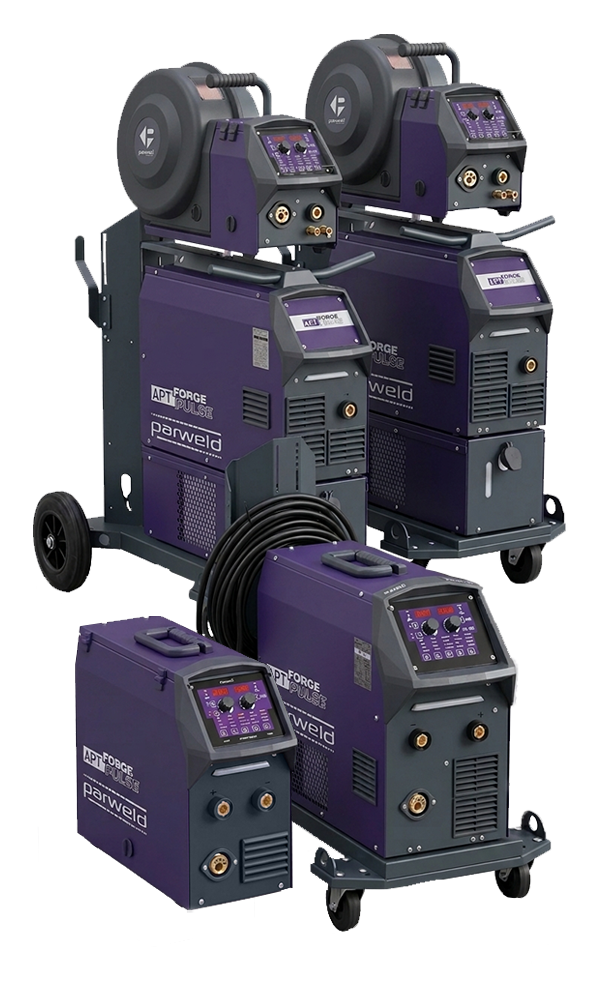
APT Forge Pulse Machines
Welcome to the pinnacle of Parweld engineering. The APT (Advanced Power Technology) brand represents our uncompromising commitment to industrial performance, precision, and technological innovation. Built for professionals who demand flawless execution on every joint, APT Forge Pulse machines are designed to push the boundaries of what is possible in modern fabrication.

Stores Up To 99 Programs

Wire Push, Pull-Back, Gas Testing

In Up To 15 Minutes

RL Torch And Cable Calabration

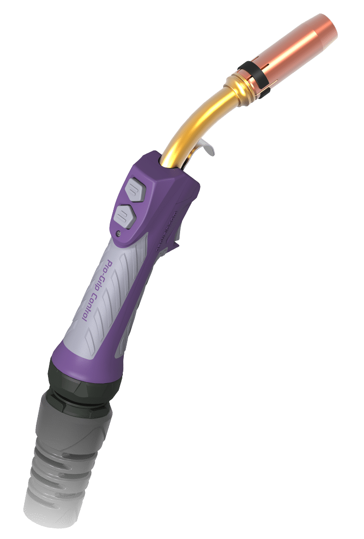
Compatible With PRO-Grip Control™ MIG/MAG Torches
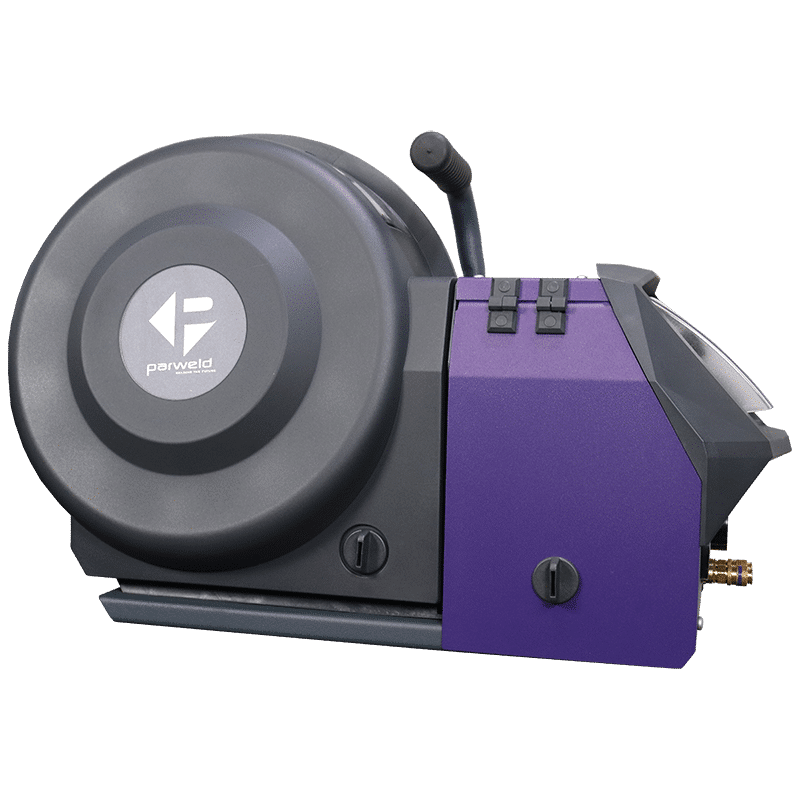
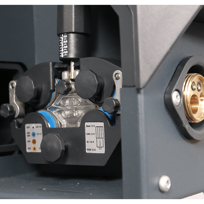
With Wire View

25.000 PPS Wire Speed Control

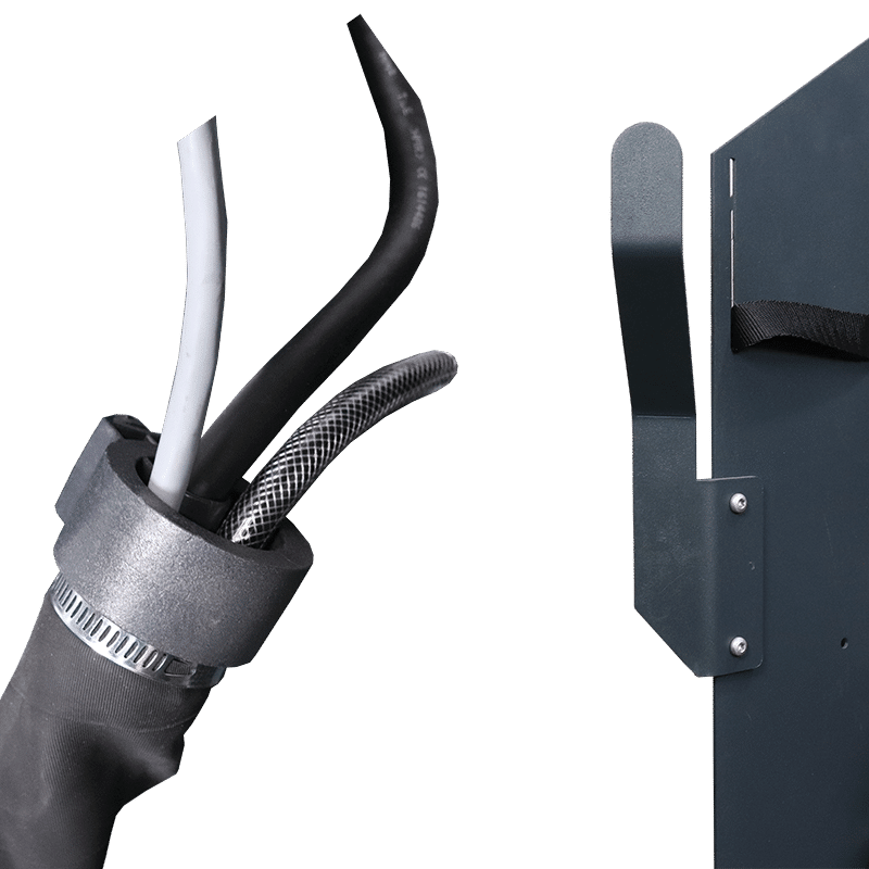
Protects Connections & Extends Cable Life
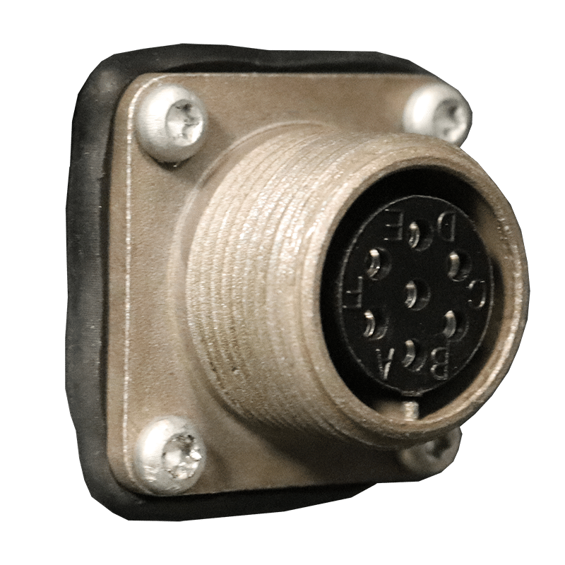
To Withstand Tough Workshop Environments
Compatible With PRO-Grip Control™ MIG/MAG Torches
Pulse Welding
Pulsed MIG Welding is a process where the Power Source switches between a high and low current extremely fast. The advantage is a smooth spatter free weld with reduced overall heat input.
Welding Processes
The APT Forge Pulse Series redefines versatility by putting elite-level arc control at your fingertips. Whether you are navigating intricate positions, tackling heat-sensitive alloys, or executing high-speed industrial production, our specialised pulsing modes adapt dynamically to your workflow. Experience reduced spatter, minimised distortion, and a flawless finish across all materials.
APT Processes
Beneath the rugged exterior of the Forge Pulse Series lies our proprietary Advanced Power Technology suite. These specialised software algorithms modify the arc characteristics in real-time, solving the most common challenges faced by industrial fabricators—from deep groove penetration to open-root gaps.
APT FP220 Compact
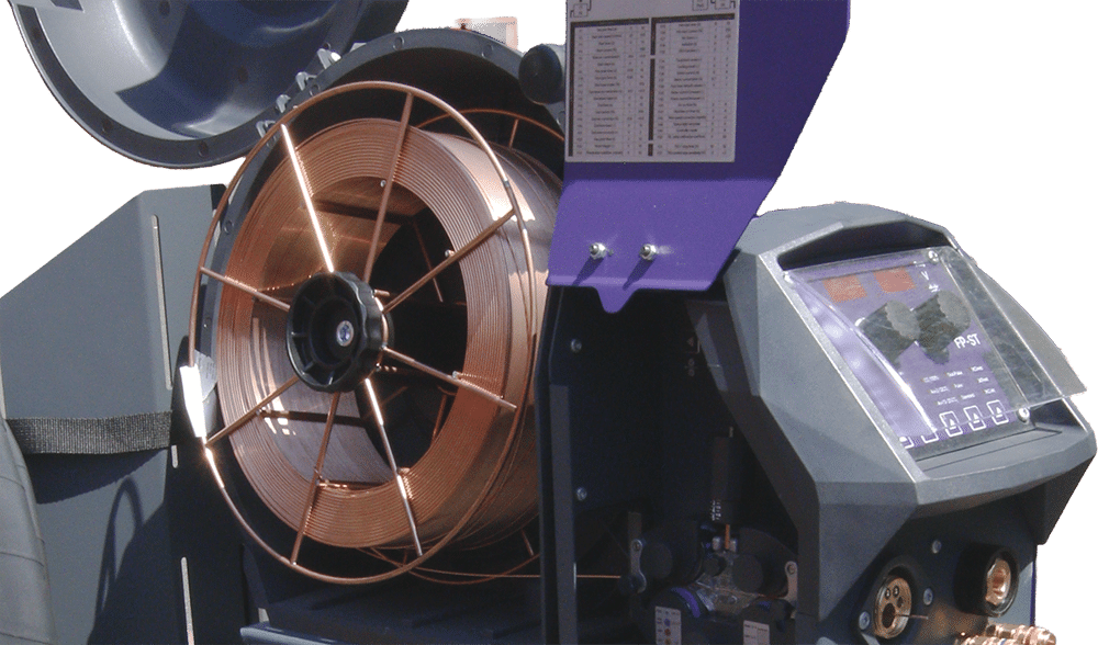
OPEN MACHINE IMAGE
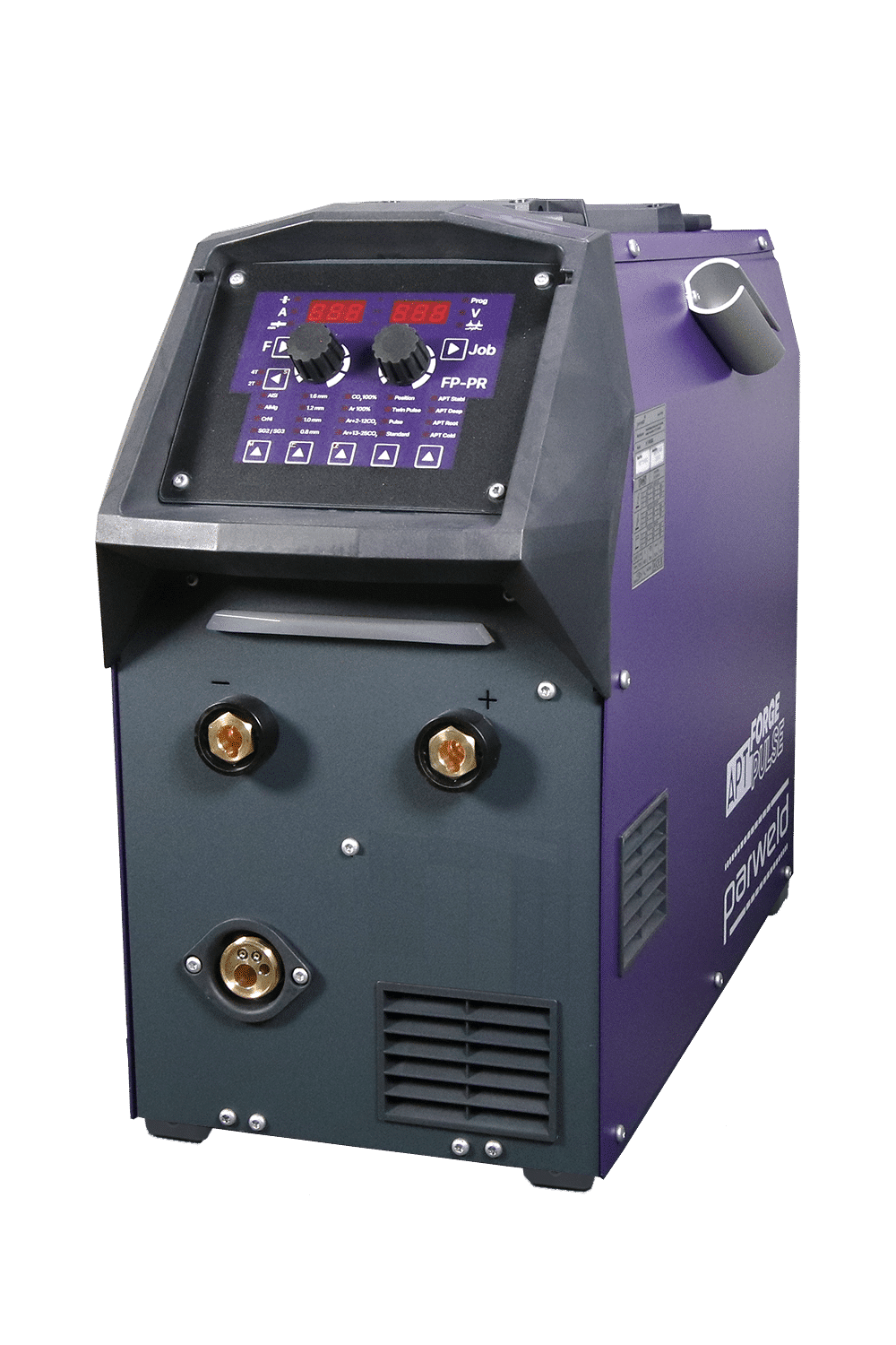
Image Shown = Air Cooled Machine with PR Panel
417mm | 16.4"
483mm | 19"
234mm | 9.2"
21kg | 3.3st
Technical Specifications
| - - - ELECTRICAL & POWER SOURCE INFORMATION - - - | |
| Input Voltage | 230V | Single Phase |
| Frequency Rating | 50/60 Hz |
| Power Source Fuse Rating | 25A |
| Mains Voltage Tolerance | -10% / +15% |
| Power Consumption (Rated) | 17.8 KW |
| Recommended Generator Size | 20 KVA |
| - - - WELDING PERFORMANCE DATA - - - | |
| Welding Current Range | 30A – 220A |
| Output Load Voltage Rating | 14.15V – 34.5V |
| Output Open Circuit Voltage | 60V |
| Duty Cycle (40°C) | 220A @ 40% | 200A @ 60% | 170A @ 100% |
- Machine Comes Equipped With = 5m Power Cable ( 4 x 2.5mm² ) | 5m Earth Clamp ( 50mm² ) | Gas Hose ( 1.5m )
-
Download User Manual
Air Cooled | PR Panel
Air Cooled | ST Panel
Technical Information
- Length = 483mm | 19″
- Width = 234mm | 9.2″
- Height = 417mm | 16.4″
- Weight = 21kg | 3.3st
| Input Voltage | 230V | Single Phase |
| Frequency Rating | 50/60 Hz |
| Power Source Fuse Rating | 25A |
| Mains Voltage Tolerance | -10% / +15% |
| Power Consumption (Rated) | 17.8 KW |
| Recommended Generator Size | 20 KVA |
| Welding Current Range | 30A – 220A |
| Output Load Voltage Rating | 14.15V – 34.5V |
| Output Open Circuit Voltage | 60V |
| Duty Cycle (40°C) | 220A @ 40% | 200A @ 60% | 170A @ 100% |
APT FP353 Compact
OPEN MACHINE IMAGE
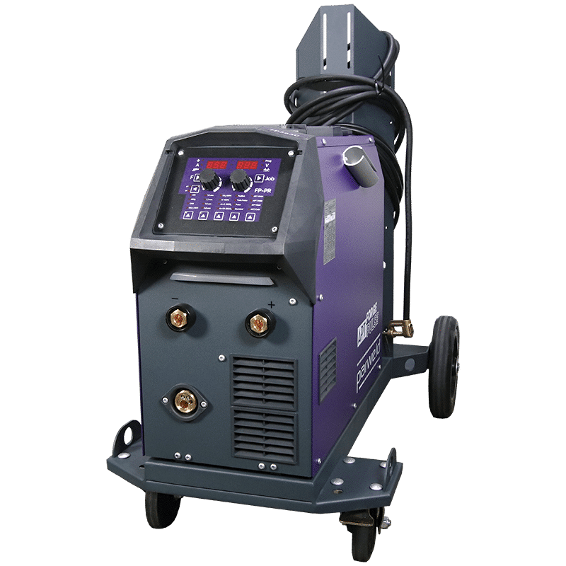
Image Shown = Air Cooled Machine with PR Panel
974mm | 38.3"
860mm | 33.8"
532mm | 20.9"
55kg | 8.7st
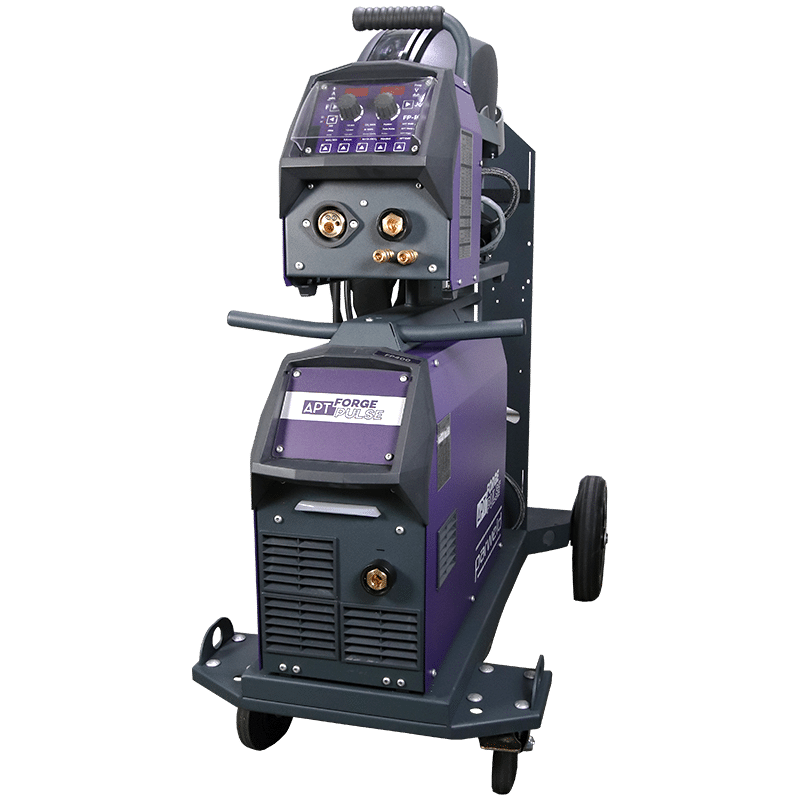
Technical Specifications
| - - - ELECTRICAL & POWER SOURCE INFORMATION - - - | |
| Input Voltage | 400V | 3 Phase |
| Frequency Rating | 50/60 Hz |
| Power Source Fuse Rating | 40A |
| Mains Voltage Tolerance | -10% / +15% |
| Power Consumption (Rated) | 24.8 KW |
| Recommended Generator Size | 20 KVA |
| - - - WELDING PERFORMANCE DATA - - - | |
| Welding Current Range | 30A – 350A |
| Output Load Voltage Rating | 14.15V – 39V |
| Output Open Circuit Voltage | 63V – 82V |
| Duty Cycle (40°C) | 350A @ 40% | 300A @ 60% | 250A @ 100% |
- Air Cooled Package Includes = 5m Power Cable ( 4 x 2.5mm² ) | 5m Earth Clamp ( 50mm² ) | Gas Hose ( 1.5m ) | Trolley Accessory
- Water Cooled Package Includes = 5m Power Cable ( 4 x 2.5mm² ) | 5m Earth Clamp ( 50mm² ) | Interconnection H.P ( 5m ) | Trolley Accessory with Water Cooler Unit
- Download User Manual
Air Cooled | PR Panel
Water Cooled | PR Panel
Air Cooled | ST Panel
Water Cooled | ST Panel
Technical Information
- Length = 860mm | 33.8″
- Width = 532mm | 20.9″
- Height = 974mm | 38.3″
- Weight = 55kg | 8.7st
| Input Voltage | 400V | 3 Phase |
| Frequency Rating | 50/60 Hz |
| Power Source Fuse Rating | 40A |
| Mains Voltage Tolerance | -10% / +15% |
| Power Consumption (Rated) | 24.8 KW |
| Recommended Generator Size | 20 KVA |
| Welding Current Range | 30A – 350A |
| Output Load Voltage Rating | 14.15V – 39V |
| Output Open Circuit Voltage | 63V – 82V |
| Duty Cycle (40°C) | 350A @ 40% | 300A @ 60% | 250A @ 100% |
APT FP400 Separate
OPEN MACHINE IMAGE
Image Shown = Air Cooled Machine with PR Panel
1178mm | 46.4"
974mm | 38.3"
532mm | 21"
94kg | 14.8st
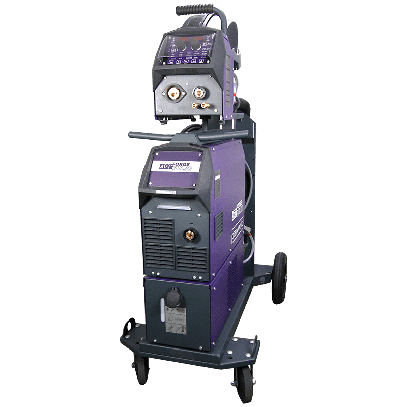
Technical Specifications
| - - - ELECTRICAL & POWER SOURCE INFORMATION - - - | |
| Input Voltage | 400V | 3 Phase |
| Frequency Rating | 50/60 Hz |
| Power Source Fuse Rating | 40A |
| Mains Voltage Tolerance | -10% / +15% |
| Power Consumption (Rated) | 24.8 KW |
| Recommended Generator Size | 24 KVA |
| - - - WELDING PERFORMANCE DATA - - - | |
| Welding Current Range | 30A – 400A |
| Output Load Voltage Rating | 14.15V – 39V |
| Output Open Circuit Voltage | 63V – 82V |
| Duty Cycle (40°C) | 400A @ 40% | 360A @ 60% | 300A @ 100% |
- Air Cooled Package Includes = 5m Power Cable ( 4 x 2.5mm² ) | 5m Earth Clamp ( 50mm² ) | Gas Hose ( 1.5m ) | Trolley Accessory
- Water Cooled Package Includes = 5m Power Cable ( 4 x 2.5mm² ) | 5m Earth Clamp ( 50mm² ) | Interconnection H.P ( 5m ) | Trolley Accessory with Water Cooler Unit
- Download User Manual
Air Cooled | PR Panel
Water Cooled | PR Panel
Air Cooled | ST Panel
Water Cooled | ST Panel
Technical Information
- Length = 974mm | 38.3″
- Width = 532mm | 20.9″
- Height = 1178mm | 46.4″
- Weight = 94kg | 14.8st
| Input Voltage | 400V | 3 Phase |
| Frequency Rating | 50/60 Hz |
| Power Source Fuse Rating | 40A |
| Mains Voltage Tolerance | -10% / +15% |
| Power Consumption (Rated) | 24.8 KW |
| Recommended Generator Size | 24 KVA |
| Welding Current Range | 30A – 400A |
| Output Load Voltage Rating | 14.15V – 39V |
| Output Open Circuit Voltage | 63V – 82V |
| Duty Cycle (40°C) | 400A @ 40% | 360A @ 60% | 300A @ 100% |
APT FP500 Separate
OPEN MACHINE IMAGE
Image Shown = Water Cooled Machine with PR Panel
1261mm | 49.6"
970mm | 38.1"
532mm | 20.9"
107kg | 16.8st
Technical Specifications
| - - - ELECTRICAL & POWER SOURCE INFORMATION - - - | |
| Input Voltage | 400V | 3 Phase |
| Frequency Rating | 50/60 Hz |
| Power Source Fuse Rating | 40A |
| Mains Voltage Tolerance | -10% / +15% |
| Power Consumption (Rated) | 24.8 KW |
| Recommended Generator Size | 34 KVA |
| - - - WELDING PERFORMANCE DATA - - - | |
| Welding Current Range | 30A – 500A |
| Output Load Voltage Rating | 14.15V – 39V |
| Output Open Circuit Voltage | 63V – 82V |
| Duty Cycle (40°C) | 500A @ 40% | 430A @ 60% | 400A @ 100% |
- Air Cooled Package Includes = 5m Power Cable ( 4 x 2.5mm² ) | 5m Earth Clamp ( 50mm² ) | Gas Hose ( 1.5m ) | Trolley Accessory
- Water Cooled Package Includes = 5m Power Cable ( 4 x 2.5mm² ) | 5m Earth Clamp ( 50mm² ) | Interconnection H.P ( 5m ) | Trolley Accessory with Water Cooler Unit
- Download User Manual
Air Cooled | PR Panel
Water Cooled | PR Panel
Air Cooled | ST Panel
Water Cooled | ST Panel
Technical Information
- Length = 970mm | 38.1″
- Width = 532mm | 20.9″
- Height = 1261mm | 49.6″
- Weight = 107kg | 16.8st
| Input Voltage | 400V | 3 Phase |
| Frequency Rating | 50/60 Hz |
| Power Source Fuse Rating | 40A |
| Mains Voltage Tolerance | -10% / +15% |
| Power Consumption (Rated) | 24.8 KW |
| Recommended Generator Size | 34 KVA |
| Welding Current Range | 30A – 500A |
| Output Load Voltage Rating | 14.15V – 39V |
| Output Open Circuit Voltage | 63V – 82V |
| Duty Cycle (40°C) | 500A @ 40% | 430A @ 60% | 400A @ 100% |
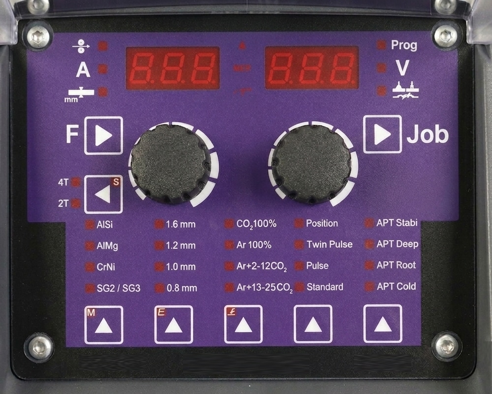
PR Panel
For All Types Of Metal Work (Steel, Cr, Cu and Al). View the Jobs List below.
| 0.8mm | 1.0mm | 1.2mm | 1.6mm | ||
|---|---|---|---|---|---|
| SG2 / SG3 | Ar+18%CO₂ | 8 | 10 | 12 | 16 |
| Ar+10%CO₂ | 18 | 20 | 22 | 26 | |
| CO₂ 100% | 28 | 30 | 32 | 36 | |
| CrNi 308 / 316 / 318 / 19 9 / 19 12 3 | Ar+2.5%CO₂ | 68 | 70 | 72 | 76 |
| CuSi | Ar100% | 178 | 180 | 182 | 186 |
| CuAl | Ar100% | 188 | 190 | 192 | 196 |
| AlMg4,5 Mn | Ar100% | 118 | 120 | 122 | 126 |
| AlSi | Ar100% | 138 | 140 | 142 | 146 |
| 0.8mm | 1.0mm | 1.2mm | 1.6mm | ||
|---|---|---|---|---|---|
| Steel / FC Metal | Ar+18%CO₂ | 238 | 240 | 242 | 246 |
| Steel / FC Rutil | Ar+18%CO₂ | 248 | 250 | 252 | 256 |
| CO₂ 100% | 262 | 266 | |||
| Steel / FC Basic | Ar+18%CO₂ | 602 | |||
| CrNi / FC Metal | Ar+2.5%CO₂ | 272 | 276 | ||
| CrNi / FC Rutil | Ar+18%CO₂ | 282 | 286 | ||
| CrNi / FC Rutil | CO₂ 100% | 292 | 296 | ||
| Steel / FC High Str. | Ar+18%CO₂ | 592 | |||
| Steel / FC Rutil | Self Shielded | 720 | 722 | ||
| 0.8mm | 1.0mm | 1.2mm | 1.6mm | ||
|---|---|---|---|---|---|
| SG2 / SG3 | Ar+18%CO₂ | 298 | 300 | 302 | 306 |
| Ar+10%CO₂ | 308 | 310 | 312 | 316 | |
| CrNi 308 / 316 / 318 / 19 9 / 19 12 3 | Ar+2.5%CO₂ | 640 | 642 | 646 | |
| AlMg4,5 Mn | Ar100% | 332 | 336 | ||
| AlSi | Ar100% | 342 | 346 | ||
| 0.8mm | 1.0mm | 1.2mm | 1.6mm | ||
|---|---|---|---|---|---|
| SG2 / SG3 | Ar+18%CO₂ | 360 | 362 | ||
| CO₂ 100% | 370 | 372 | |||
| Ar+10%CO₂ | 500 | 502 | |||
| 0.8mm | 1.0mm | 1.2mm | 1.6mm | ||
|---|---|---|---|---|---|
| SG2 / SG3 | Ar+18%CO₂ | 378 | 380 | 382 | 386 |
| CO₂ 100% | 388 | 390 | 392 | ||
| Ar+10%CO₂ | 510 | 512 | |||
| CrNi 308 / 316 / 318 / 19 9 / 19 12 3 | Ar+2.5%CO₂ | 398 | 400 | 402 | |
| MIG/MAG Manual | 4 | ||||
| TIG (Lift Arc) | 5 | ||||
| MMA | 6 | ||||
| Gouging | 7 | ||||
Wire Feed Speed
Welding Current
Material Thickness Selection
Menu Selection / Press and Hold Function Settings
Trigger Selection
Material Type Selection / Press and Hold
for Manual Welding
Wire Diameter Selection / Press and Hold for TIG Welding
Shielding Gas Selection / Press and Hold for MMA Welding
Standard Process Selection
Special Process Selection
Menu Selection Press and Hold / Job Settings
Inductance
Voltage
Program Memory
Hold Indicator
Lock Indicator
Trigger Indicator
| Function | Description | Minimum | Maximum |
|---|---|---|---|
| F1 | Gas pre-flow (s) | 0 | 10 |
| F2 | Start wire speed (m/min) | 20 | 100 |
| F3 | Start time (s) | 0 | 10 |
| F4 | Start current (%) | 1 | 200 |
| F5 | Start arc correction(V) | -9.9 | +9.9 |
| F7 | Start slope (s) | 0 | 5 |
| F8 | Duo peak time (s) | 0.05 | 10 |
| F10 | Duo base time (s) | 0.05 | 10 |
| F11 | Duo base amper (%) | 1 | 100 |
| F12 | Duo base arc correction (v) | -9.9 | +9.9 |
| F15 | End down slope (s) | 0 | 10 |
| F16 | End time (s) | 0 | 10 |
| F17 | End current (%) | 1 | 200 |
| F18 | End arc correction (V) | -9.9 | +9.9 |
| F20 | End burn back (-) | 0 | 15 |
| F21 | End wire cut mode (-) | 0 | 2 |
| F22 | Gas post-flow (s) | 0 | 10 |
| F23 | Smart trigger (-) | 0 | 10 |
| F24 | Penetration stabilizer (m/min) | 0 | 10 |
| Function | Description | Minimum | Maximum |
|---|---|---|---|
| F25 | Hot start time (s) | 0 | 10 |
| F26 | Hot start current (%) | 1 | 200 |
| F27 | Arc force (-) | 0 | +50 |
| F28 | Antistick (s) | 0 | 2 |
| F29 | VRD function (-) | 0 | 1 |
| Function | Description | Minimum | Maximum |
|---|---|---|---|
| F34 | Tack/stich mode (-) | 0 | 2 |
| F35 | Cooling mode (-) | 0 | 4 |
| F36 | Motor current (A) | 0 | 4 |
| F37 | Motor current limit (A) | 0.7 | 7 |
| F38 | Auto load default values (-) | 0 | 1 |
| F39 | Motor control firmware (-) | – | – |
| F40 | Power control firmware (-) | – | – |
| F41 | Arc on time (h) | 0 | 4 |
| F42 | Machine on time (h) | 0 | 4 |
| F45 | Wire speed correction (m/min) | -2 | +2 |
| F48 | Status light template | 0 | 4 |
| F49 | Controller mode | 0 | 9 |
| F50 | RL cable calibration (mOhm) | 0 | 30 |
| Function | Description | Minimum | Maximum |
|---|---|---|---|
| F31 | TIG V stop limit (V) | 18 | 18 |
| F32 | TIG comfort stop sensitivity (V) | -2 | +2 |
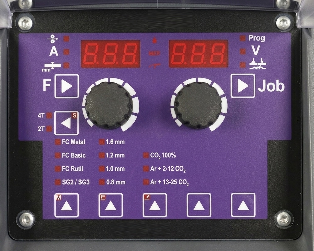
ST Panel
For Flux-Cored Wire And Steel Solutions. View the Jobs List below.
| 0.8mm | 1.0mm | 1.2mm | 1.6mm | ||
|---|---|---|---|---|---|
| SG2 / SG3 | Ar+18%CO₂ | 8 | 10 | 12 | 16 |
| Ar+10%CO₂ | 18 | 20 | 22 | 26 | |
| CO₂ 100% | 28 | 30 | 32 | 36 | |
| CrNi 308 / 316 / 318 / 19 9 / 19 12 3 | Ar+2.5%CO₂ | 68 | 70 | 72 | 76 |
| CuSi | Ar100% | 178 | 180 | 182 | 186 |
| CuAl | Ar100% | 188 | 190 | 192 | 196 |
| AlMg4,5 Mn | Ar100% | 118 | 120 | 122 | 126 |
| AlSi | Ar100% | 138 | 140 | 142 | 146 |
| 0.8mm | 1.0mm | 1.2mm | 1.6mm | ||
|---|---|---|---|---|---|
| Steel / FC Metal | Ar+18%CO₂ | 238 | 240 | 242 | 246 |
| Steel / FC Rutil | Ar+18%CO₂ | 248 | 250 | 252 | 256 |
| CO₂ 100% | 262 | 266 | |||
| Steel / FC Basic | Ar+18%CO₂ | 602 | |||
| CrNi / FC Metal | Ar+2.5%CO₂ | 272 | 276 | ||
| CrNi / FC Rutil | Ar+18%CO₂ | 282 | 286 | ||
| CrNi / FC Rutil | CO₂ 100% | 292 | 296 | ||
| Steel / FC High Str. | Ar+18%CO₂ | 592 | |||
| Steel / FC Rutil | Self Shielded | 720 | 722 | ||
| 0.8mm | 1.0mm | 1.2mm | 1.6mm | ||
|---|---|---|---|---|---|
| SG2 / SG3 | Ar+18%CO₂ | 298 | 300 | 302 | 306 |
| Ar+10%CO₂ | 308 | 310 | 312 | 316 | |
| CrNi 308 / 316 / 318 / 19 9 / 19 12 3 |
Ar+2.5%CO₂ | 640 | 642 | 646 | |
| AlMg4,5 Mn | Ar100% | 332 | 336 | ||
| AlSi | Ar100% | 342 | 346 | ||
| 0.8mm | 1.0mm | 1.2mm | 1.6mm | ||
|---|---|---|---|---|---|
| SG2 / SG3 | Ar+18%CO₂ | 360 | 362 | ||
| CO₂ 100% | 370 | 372 | |||
| Ar+10%CO₂ | 500 | 502 | |||
| 0.8mm | 1.0mm | 1.2mm | 1.6mm | ||
|---|---|---|---|---|---|
| SG2 / SG3 | Ar+18%CO₂ | 378 | 380 | 382 | 386 |
| CO₂ 100% | 388 | 390 | 392 | ||
| Ar+10%CO₂ | 510 | 512 | |||
| MIG/MAG Manual | 4 | ||||
| TIG (Lift Arc) | 5 | ||||
| MMA | 6 | ||||
| Gouging | 7 | ||||
Wire Feed Speed
Welding Current
Material Thickness Selection
Menu Selection / Press and Hold Function Settings
Trigger Selection
Material Type Selection / Press and Hold
for Manual Welding
Wire Diameter Selection / Press and Hold for TIG Welding
Shielding Gas Selection / Press and Hold for MMA Welding
Standard Process Selection
Special Process Selection
Menu Selection Press and Hold / Job Settings
Inductance
Voltage
Program Memory
Hold Indicator
Lock Indicator
Trigger Indicator
| Function | Description | Minimum | Maximum |
|---|---|---|---|
| F1 | Gas pre-flow (s) | 0 | 10 |
| F2 | Start wire speed (m/min) | 20 | 100 |
| F3 | Start time (s) | 0 | 10 |
| F4 | Start current (%) | 1 | 200 |
| F5 | Start arc correction(V) | -9.9 | +9.9 |
| F7 | Start slope (s) | 0 | 5 |
| F8 | Duo peak time (s) | 0.05 | 10 |
| F10 | Duo base time (s) | 0.05 | 10 |
| F11 | Duo base amper (%) | 1 | 100 |
| F12 | Duo base arc correction (v) | -9.9 | +9.9 |
| F15 | End down slope (s) | 0 | 10 |
| F16 | End time (s) | 0 | 10 |
| F17 | End current (%) | 1 | 200 |
| F18 | End arc correction (V) | -9.9 | +9.9 |
| F20 | End burn back (-) | 0 | 15 |
| F21 | End wire cut mode (-) | 0 | 2 |
| F22 | Gas post-flow (s) | 0 | 10 |
| F23 | Smart trigger (-) | 0 | 10 |
| F24 | Penetration stabilizer (m/min) | 0 | 10 |
| Function | Description | Minimum | Maximum |
|---|---|---|---|
| F25 | Hot start time (s) | 0 | 10 |
| F26 | Hot start current (%) | 1 | 200 |
| F27 | Arc force (-) | 0 | +50 |
| F28 | Antistick (s) | 0 | 2 |
| F29 | VRD function (-) | 0 | 1 |
| Function | Description | Minimum | Maximum |
|---|---|---|---|
| F34 | Tack/stich mode (-) | 0 | 2 |
| F35 | Cooling mode (-) | 0 | 4 |
| F36 | Motor current (A) | 0 | 4 |
| F37 | Motor current limit (A) | 0.7 | 7 |
| F38 | Auto load default values (-) | 0 | 1 |
| F39 | Motor control firmware (-) | – | – |
| F40 | Power control firmware (-) | – | – |
| F41 | Arc on time (h) | 0 | 4 |
| F42 | Machine on time (h) | 0 | 4 |
| F45 | Wire speed correction (m/min) | -2 | +2 |
| F48 | Status light template | 0 | 4 |
| F49 | Controller mode | 0 | 9 |
| F50 | RL cable calibration (mOhm) | 0 | 30 |
| Function | Description | Minimum | Maximum |
|---|---|---|---|
| F31 | TIG V stop limit (V) | 18 | 18 |
| F32 | TIG comfort stop sensitivity (V) | -2 | +2 |
APT Accessory Items
APT FP4 Wire Feeder

Fitted to the FP 400 and FP 500 Machines, the APT FP4 Wire Feeder Unit is a heavy-duty, separate wire feeding powerhouse, engineered for demanding industrial fabrication environments. Featuring a robust 4-roll wire drive assembly that ensures positive, slip-free feeding and perfect consistency even when utilising extended interconnecting cable packages. Optimised for advanced digital synchronisation, effortlessly communicating with the main power source to manage the ultra-high-speed 25,000 pulses-per-second wire control loop, facilitating advanced processes like Deep, Root, and Twin-Pulse with flawless arc stability.
APT Water Cooler Unit

High-Performance, modular cooling system engineered specifically as an option for the Forge Pulse FP 353, FP 400 and FP 500 power source models. Designed to handle the extreme thermal demands of high-amperage spray transfer and prolonged pulse welding, the unit delivers consistent torch cooling to protect consumables and maintain arc stability during heavy-duty production cycles.
For maximum efficiency, rather than running continuously at full capacity, the power source actively monitors internal temperatures and torch usage to cycle the water cooler's pump and fan only when required.
APT Trolley Assembly

The heavy-duty workshop trolley, fitted as standard to the FP 353, FP 400 and FP 500 models, is engineered to turn these industrial power sources into highly mobile, self-contained welding stations. Built to withstand the harsh environments of busy fabrication shops and manufacturing facilities, the trolley features a rugged, reinforced steel chassis that easily supports the combined weight of the power source, an optional water cooling unit, and a full wire feeder package.

Check out your nearest Parweld distributor for more on Welding Inverters available to you.
Or alternatively, contact Parweld Head Office for more details.